Tuesday 26 January 2016

Correcting vignetting in digital photographs — software

In a previous blog post I outlined how I correct vignetting in digital photographs. In this post I will describe in more detail the software I've written to do this. The corrector is part of my Pyctools project and you can download example scripts that use it from my Pyctools-demo project.

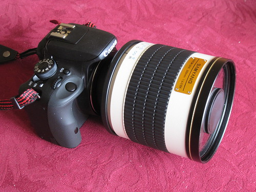
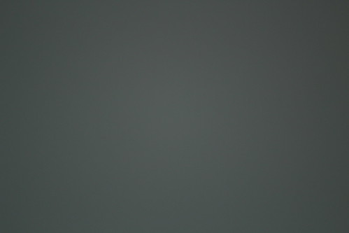
The picture below shows the component network used to determine the vignette correction parameters for a particular lens. (Click on the image to view the full resolution version on Flickr.) It requires a photograph of an evenly illuminated plain surface such as a grey card.

Vignette correction screen grab

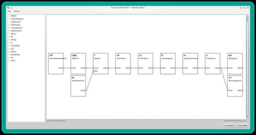
The network contains the following components (from left to right):
  1. RawImageFileReader() — reads the grey image file. This is set to output linear data, i.e. no gamma correction is applied. (If the grey image is not a raw file then an inverse gamma corrector is needed between the file reader and the next component.)
  2. RGBtoY() — converts the RGB image to luminance.
  3. Resize() — reduces the image size to fit on the computer screen.
  4. Arithmetic() — averages the image with its horizontal reflection.
  5. Arithmetic() — averages the image with its vertical reflection. These two stages reduce the effect of uneven illumination in the original photograph.
  6. FrameRepeat() — converts the still to a video sequence. This allows the vignette corrector parameters to be adjusted "live", with near instant effect on the displayed image and histogram.
  7. VignetteCorrector() — applies the radially varying gain.
  8. Arithmetic() — boosts the image contrast. This makes any residual vignetting easier to see.
  9. QtDisplay() — shows the video. The frame rate is set to 5Hz, as this is fast enough to give feedback as the parameters are adjusted.
  10. ShowHistogram() — shows the video's histogram. This helps when adjusting the contrast boost.

Before running the network I open the configuration dialogs of the vignette corrector and contrast booster. This allows these components to be adjusted while the graph is running, as shown below.

Vignette correction screen grab

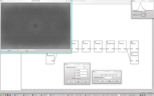
The top left window shows the image after vignette correction, with a contrast boost of 64x in this example. The top right window shows the histogram of this contrast enhanced image. You can see there is still some residual variation in brightness, including an interesting slight darkening at the centre. The lighter patches at top and bottom make it hard to assess the effect of small changes in the vignette corrector settings. However, I think that this result is good enough for all practical purposes.

Automatic parameter setting


Since writing the above I've written software to automate the process. It measures the average level of 50 annular bands of a grey card image, computes the gain required to correct each band, then fits a 3rd order polynomial to the gain and prints out the appropriate vignette corrector settings. The above process can then be used to check the settings.

I've also identified the cause of the slight darkening at the centre of the corrected image. Using a polynomial function does not produce a good fit at zero radius, as shown in this graph.


The blue line is the required gain computed from image data and the green line is the fitted function.

Further reading


The vignette corrector component is written in Python and uses NumPy to do all the hard work. You can view the source code on GitHub and its documentation on ReadTheDocs.org.

Example scripts to determine the corrector settings and to process photographs are also downloadable from GitHub.

Sunday 24 January 2016

Correcting vignetting in digital photographs — introduction

I recently purchased a budget telephoto lens for my Canon EOS 100D DSLR camera. It's a 500mm f/6.3 mirror lens, essentially a small Cassegrain telescope. Like many budget lenses it suffers from "vignetting", i.e. the edges of a photograph are darker than the centre.

500mm f/6.3 mirror lens

The EOS 100D camera has built in vignette correction (called peripheral illumination correction in the camera's menu) but this only works with Canon lenses for which the camera has data1. Also it is only applied to JPEG images, the raw image files are uncorrected. When processing raw images, or images taken with non-Canon lenses (such as a telescope), I need to apply vignette correction on my Linux computer. In my next blog post I'll describe the software I've written (as part of my Pyctools project) in more detail. This is a general introduction.

The picture below shows the vignetting problem. It's a subtle effect which may not be that visible, as the eye is very good at ignoring gradual changes in illumination. We evolved in an unevenly lit world. It is also less visible in pictures with lots of detail. A plain clear sky is probably the most testing subject. (Click on a picture to see the full size version on Flickr.)

Winter daytime moon

After correction the sky is a much more even blue, as shown below. Comparing the two might make you think I've over-done the correction, but I'm fairly sure I haven't.

Winter daytime moon

Processing


The processing involved is actually quite simple. Vignetting is a reduction of light that varies with distance from the centre of the image, so correcting it requires multiplying the image pixel values by an amount that also varies with distance from the centre of the image. The tricky bit is determining how much correction to apply at each radius.

I start by photographing a plain grey card, illuminated as evenly as I can manage, using the lens (and lens settings) that I want to correct for. With my budget mirror lens or an astronomical telescope the focal length and aperture are fixed, so I just have to make sure the focus distance is correct.

Vignetting measurements

I then process the photograph with my vignette correction software and adjust its parameters until the output shows minimum radial variation. To check this I multiply the corrected image data by increasing amounts (4, 8, 16, etc.) as I get nearer the optimum settings. Eventually the unevenness of the card's illumination is the dominant factor. I can then store the vignette corrector settings, knowing they will be applicable to other pictures taken with that lens.

At this point you might be thinking what about gamma correction? The vignette correction needs to be applied to linear intensity, so should be done before the raw image data is gamma corrected for storage in JPEG or similar formats, i.e. as part of the raw image processing. In the moon examples shown above I didn't capture raw images, so I applied an inverse gamma function before correcting the vignette and then gamma correcting again.


[1] I got some odd results when I first started using the 500mm mirror lens. I'm using a T adaptor with a focus confirmation "chip" that the camera recognised as a Canon 50mm f/1.8 lens and applied that lens's correction data. I cured this problem by using Canon's software to remove all lens data from the camera except the Canon lens I have.