A few months ago I converted my N gauge train set to DCC operation. As well as fitting DCC decoders to my locomotives I also converted the points by fitting a tiny decoder in each one.
This makes setting up a temporary layout (I don't yet have any sort of permanent layout) nice and easy (as there's no point wiring to worry about) but operating accessories such as points from the NCE PowerCab controller is a bit of a faff. First you press the "accy" button, then select the number, then "enter", then "on" or "off". Half the time you've misremembered the last state of that point so the command has no effect, so you then have to press the "accy" button twice to toggle it.
NCE controllers can be linked together via a system called "Cab Bus". This uses a fairly simple protocol that allows subsidiary controllers to send commands to the main controller (the PowerCab in my case) which then sends the corresponding DCC commands to the track. I decided to make a simple controller to switch my points, using an Arduino. I've never used an Arduino before and I thought this would be a good starter project. I found this useful page that gave me all the information I needed.
I decided to use an Arduino Nano Every as it's quite small, has a serial interface that's separate from its USB port, and has a switching voltage regulator to allow it to run efficiently from the Cab Bus 12 V supply. The other main components are an RS485 to TTL converter, a pair of RJ11 sockets, and push buttons & LEDs.

I used two RJ11 sockets to provide "loop through" to another controller (possibly) or an RS485 to USB interface used to monitor the Cab Bus during development. I wrote a simple Python script to show the polling frequency of each polled address and display any non-polling bytes on the bus.
from collections import defaultdict
import sys
import time

import serial


def main():
    with serial.Serial('/dev/ttyUSB0', baudrate=9600,
                       bytesize=serial.EIGHTBITS, parity=serial.PARITY_NONE,
                       stopbits=serial.STOPBITS_TWO) as bus:
        period = 15.0
        last_byte = None
        while True:
            pings = defaultdict(int)
            stop = time.time() + period
            while time.time() < stop:
                data = ord(bus.read(1))
                if (data & 0b11000000) == 0b10000000:
                    # ping byte
                    if last_byte is None:
                        print()
                    pings[data] += 1
                    last_byte = data
                else:
                    # data byte
                    if last_byte is not None:
                        print('... {:02x}'.format(last_byte), end='')
                        last_byte = None
                    print(' {:02x}'.format(data), end='')
            print()
            for key in sorted(pings.keys()):
                print('{:02x}: {:3.2f} Hz'.format(key, pings[key] / period))
    return 0


if __name__ == '__main__':
    sys.exit(main())
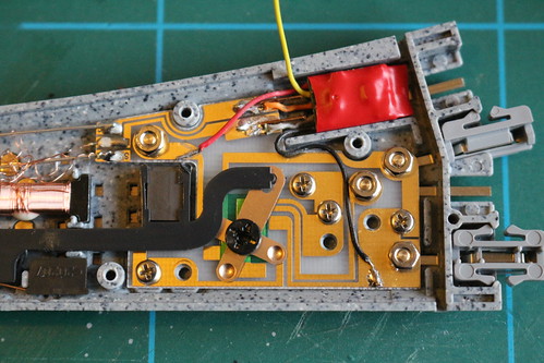
The circuit board uses "strip board" or "Vero board". I spent some time planning it (unusually for me) and finished up with a quite compact arrangement. In this diagram the gold coloured lines are tracks on the back of the board and the blue lines are wires above the board.

The Arduino "sketch" is also quite simple. It uses a struct to store the current state of each button. When a button is pressed its LEDs are toggled, and the corresponding accessory command is sent to the cab bus.
// This is a 'type c' controller, so its address should be 8, 9, or 10 when using PowerCab
const int controllerAddress = 8;

// Which serial port is connected to the Cab Bus
#define RS485 Serial1

// Connected to RS485 module's /RE and DE pins
const int txEnablePin = 10;

// Number of push button & LED sets
const int channelCount = 8;

// Configuration of each channel
struct configDetails {
  int buttonPin;  // pin connected to push button
  int ledPin;     // pin connected to "on"/"off" LED pair
  int accyAddr;   // DCC address of the controlled accessory
  bool inverted;  // swap the meanings of "on" and "off"
};
const struct configDetails configuration[channelCount] = {
  {A4, 5,  1, false},
  {A0, 9,  2,  true},
  {A5, 4,  3, false},
  {A1, 8,  4,  true},
  {A6, 3, 60, false},
  {A2, 7, 61, false},
  {A7, 2, 62, false},
  {A3, 6, 63, false},
};

// How many ms to wait for button to settle
const unsigned long DEBOUNCE_DELAY = 10;

struct channelState {
  bool on = false;        // "output" value, toggles each button press
  bool down = false;      // button is currently down
  unsigned long wait = 0; // wait until this time for the button to settle
};
struct channelState stateStore[channelCount];

void setup() {
  const struct configDetails* cnfg;
  for (int channel = 0; channel < channelCount; channel++) {
    cnfg = &configuration[channel];
    pinMode(cnfg->buttonPin, INPUT_PULLUP);
    pinMode(cnfg->ledPin, OUTPUT);
  }
  pinMode(txEnablePin, OUTPUT);
  digitalWrite(txEnablePin, LOW);
  RS485.begin(9600, SERIAL_8N2);
}

void loop() {
  const struct configDetails* cnfg;
  struct channelState* state;
  for (int channel = 0; channel < channelCount; channel++) {
    cnfg = &configuration[channel];
    state = &stateStore[channel];
    if (pollButton(cnfg->buttonPin, state)) {
      digitalWrite(cnfg->ledPin, state->on?HIGH:LOW);
      switchCabBus(cnfg->accyAddr, state->on != cnfg->inverted);
    }
  }
}

bool pollButton(const int pinNo, struct channelState* state) {
  // Return true if button "on"/"off" state has just changed
  if (state->wait != 0) {
    // waiting for stability
    if (millis() < state->wait) {
      return false;
    }
  }
  if (digitalRead(pinNo) == HIGH) {
    // button is up, so any waiting is cancelled
    state->down = false;
    state->wait = 0;
    return false;
  }
  if (state->wait != 0) {
    // button has been pressed for long enough
    state->wait = 0;
    state->on = not state->on;
    return true;
  }
  else if (not state->down) {
    // button has just been pressed
    state->down = true;
    state->wait = millis() + DEBOUNCE_DELAY;
  }
  return false;
}

void switchCabBus(const int accyAddr, const bool on) {
  unsigned char command[5];
  command[0] = 0x50 + (accyAddr >> 7);
  command[1] = accyAddr & 0x7f;
  command[2] = on?4:3;
  command[3] = 0;
  command[4] = ((command[0] ^ command[1]) ^ command[2]) ^ command[3];
  cbSend(command, 5);
}

void cbSend(unsigned char buf[], int len) {
  unsigned char rxByte;
  unsigned long timeout;
  // Empty input buffer
  while (RS485.available()) {
    rxByte = RS485.read();
  }
  timeout = millis() + 250;
  rxByte = RS485.read();
  // Swallow input until our address is polled
  while (rxByte != 0x80 + controllerAddress) {
    if (millis() > timeout) {
      // Cab Bus is probably disconnected
      return;
    }
    rxByte = RS485.read();
  }
  // Respond 100..800 µs after poll
  delayMicroseconds(150);
  // Send command
  digitalWrite(txEnablePin, HIGH);
  RS485.write(buf, len);
  RS485.flush();
  digitalWrite(txEnablePin, LOW);
}
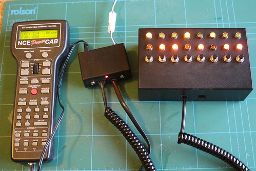
Here is the controller connected up to my PowerCab.
No comments:
Post a Comment