Showing posts with label model. Show all posts

Tuesday, 21 November 2017

AstroMedia Copernican Orrery kit - part 2

In part 1 I described the first half (approximately) of the construction of a cardboard Orrery kit from AstroMedia. In the second half things get more interesting, and more complicated, as the majority of the pulleys and shafts are assembled.

AstroMedia Copernican Orrery kit

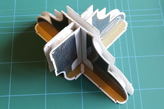
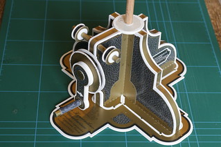
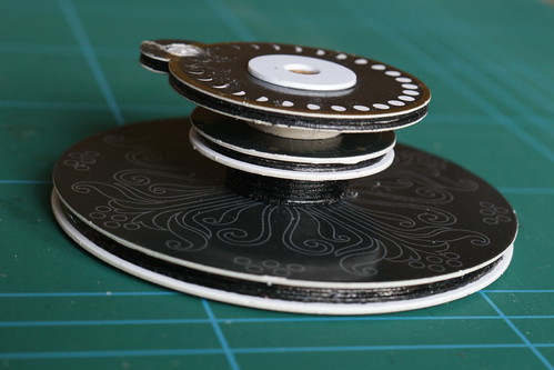
The first part to be constructed is the "planetary gearing". This will eventually roll around the ecliptic disc, held in place by drive bands above and below the ecliptic disc.
AstroMedia Copernican Orrery kit

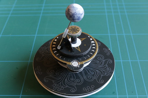
As you know, Earth's rotational axis is tilted and the Orrery has quite a clever system to keep the axis pointing in (roughly) the same direction as the Earth orbits the sun. The Earth rotates on a steel shaft which runs through a brass tube attached to a small bracket. The bracket is attached to a hollow shaft that passes through the planetary gearing to a drive wheel below.

The Earth's rotation is driven by another pulley and shaft that passes through the planetary gearing. A round magnet attached to the top drives the Earth's rotation via a small piece of silicone tubing. Unfortunately I didn't get the magnet exactly centred on the shaft and so the drive occasionally slips.
AstroMedia Copernican Orrery kit

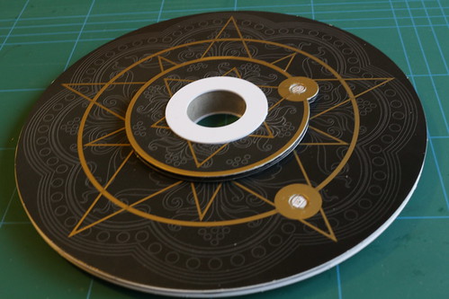
Above the ecliptic disc are two large discs supporting Mercury and Venus. The orbit of Venus is driven by a belt around its large support disc, and Mercury is driven from below by a hollow shaft through the Venus disc. After fitting all the drive belts the moon and remaining planets are attached with steel support pins.
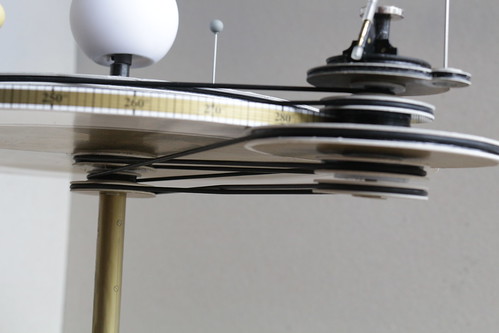
AstroMedia Copernican Orrery kit

There are five drive belts holding the planetary gearing in place. The topmost one drives the orbit of Venus, the next drives Mercury's orbit. The bottommost one drives Earth's rotation, the next keeps Earth's axis pointing in a constant direction and the last drives the planetary gearing to roll around the ecliptic disc. Does it all work? Watch the video and see for yourself.
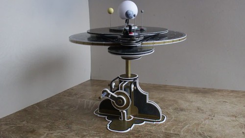
AstroMedia Copernican Orrery kit

PS More pictures of its construction are available on Flickr.

Tuesday, 14 November 2017

AstroMedia Copernican Orrery kit - part 1

AstroMedia Copernican Orrery kit

For a long time I've fancied having an Orrery but have been put off by the high price of traditional style brass ones with all the planets (and Pluto). Something much more my style is the cardboard kit from AstroMedia. This only has the inner planets, but I get the fun of building it.

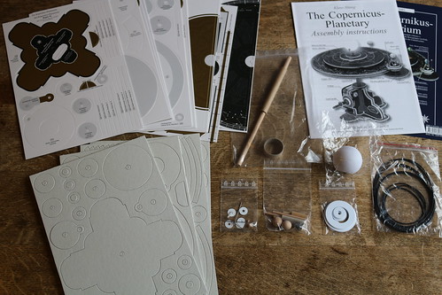
I bought the kit a few months ago from Sherwoods Photographic Ltd, a company I've bought a telescope and accessories from in the past. Two weeks ago I finally got round to starting to construct it.

I soon discovered that one of the die-cut thick card sheets was missing (and I had a duplicate of another sheet). I emailed Sherwoods and they arranged for the UK arm of AstroMedia to send me a replacement, which arrived the next day. Top notch service from both companies.

At the time of writing I'm about halfway through building the kit. So far I'm very impressed with its quality, and with the instruction leaflet, although it occasionally reveals its German language origins. Construction is quite slow as you have to allow glue to set before moving on to the next stage. I'm also doing the optional painting of some cardboard edges on partly assembled components, so I have to wait for that paint to dry as well.

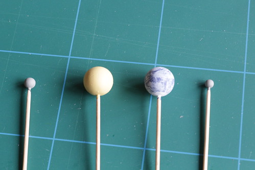
There is a temptation to read ahead and start constructing later parts, but with so many similar looking wheels it could get very confusing. One thing I have done in advance though is to paint the small wooden spheres used to represent the planets and our moon, after temporarily mounting them on cocktail sticks.

AstroMedia Copernican Orrery kit

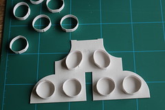
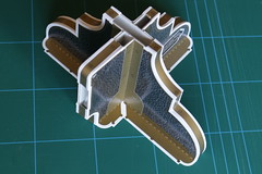
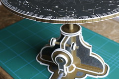
The first component to be built is the pedestal. This uses spacer rings between two sheets of card to make a strong, light structure. Strips of printed paper are used to cover the gap — a fiddly bit of glueing but the result isn't too bad.

AstroMedia Copernican Orrery kit AstroMedia Copernican Orrery kit AstroMedia Copernican Orrery kit AstroMedia Copernican Orrery kit

Next is the drive crank and pulleys, followed by the pedestal base and the central shaft with three pulleys.

AstroMedia Copernican Orrery kit AstroMedia Copernican Orrery kit

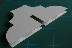
Today I finished the ecliptic disc, another structure using spacing rings. It's beginning to look like something now.

AstroMedia Copernican Orrery kit AstroMedia Copernican Orrery kit

PS Part two is now available. More pictures of its construction are available on Flickr.
Tuesday, 15 November 2016

Replumbing my toy traction engine

The steam valve on Wilesco toy traction engines (and steam rollers) is rather basic. It has a plastic lever, which is loose when cold, and goes from closed to fully open in less than a quarter turn, making it rather difficult to set the engine speed precisely.

I decided to replace it with a better quality "globe" valve to give finer control, and to move the valve to the driver's end of the engine. I also wanted to add a displacement lubricator to ensure the cylinder is always well oiled.

As Wilesco is a German company their models use metric threads throughout, whereas British steam models still use imperial sizes. I prefer to work in metric so bought all the metric fittings I needed from a German supplier Modellbau-Niggel. I was at least able to buy metric pipe from a British supplier, Macc Models.

Connecting the steam valve to the boiler


Rather than run a pipe from the original steam valve position to the driver's end of the engine I decided to move the whistle to the original valve position and connect the new valve to where the whistle had been. This would require quite a complicated bit of pipe bending with three 90° bends in close proximity.

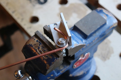
I made a simple pipe bending jig out of washers, nuts and a bolt. Cutting away the side of one of the washers allows bends to be made in close proximity, as well as making it easier to remove the bent pipe from the jig.

Replacing the Wilesco steam valve

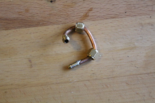
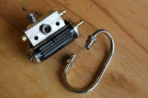
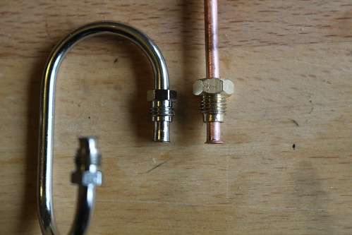
After bending the pipe and cutting it to length I soldered pipe nipples (or cones) to each end. As you can see, I used a bit too much solder on one of them.

Replacing the Wilesco steam valve

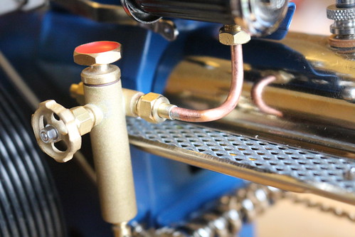
The completed globe valve connection.

Replacing the Wilesco steam valve

If you've browsed the Modellbau-Niggel web site you may have noticed that they don't sell a globe valve (or oiler) with 3mm pipe connections. I used their part number 310 425 which has an M6x0.75 threaded inlet and a 4mm pipe nipple outlet. I shortened the threaded inlet and then used a centre drill to make a seat for a 3mm pipe cone. I used a sleeve of 4mm brass tube to solder the outlet nipple to 3mm pipe.

Connecting the lubricator to the steam chest


The traction engine's "steam chest" uses a flared pipe connection with an M6x0.75 nut (or screw, as it has male threads) to clamp the flared pipe to a sealing washer. The pipe is about 3.7mm diameter, so I couldn't simply reuse the nut with my 3mm pipe.
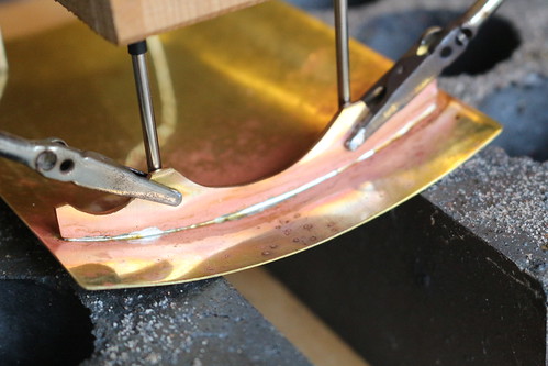
Replacing the Wilesco steam valve

Instead I used part number 706 675 which is a good fit on 3mm pipe. I cut off one side and shortened the other, then filed off the thread at the very end so it fits the steam chest. Then I flared the end of some 3mm pipe.

Replacing the Wilesco steam valve

After bending the pipe and soldering a 3mm nipple to the other end the oiler was fitted to the traction engine.

Replacing the Wilesco steam valve

As with the steam valve, the oiler I used (part number 400 104) has M6x0.75 threaded connections on which I used a centre drill to make seats for 3mm pipe nipples.

The final connection


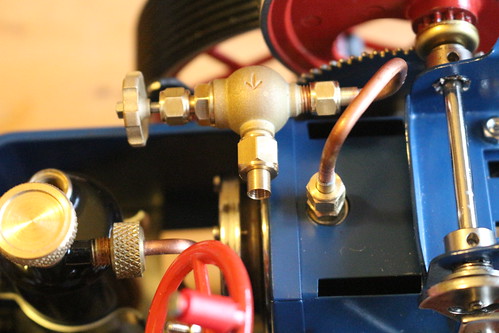
The last bit of pipework is much simpler, apart from sleeving one end to fit the 4mm outlet of the steam valve.

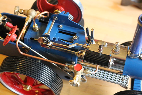
Replacing the Wilesco steam valve

Initial tests show everything is working as it should, and the new steam valve is a considerable improvement. I've yet to determine the optimum setting for the oiler's needle valve, so am erring on the generous side for now, giving it one whole turn from fully closed.

Saturday, 12 November 2016

Making a canopy for my Wilesco traction engine, part 3.

In two previous posts I discussed designing a canopy for my toy traction engine and committing the design to metal. In this post I show the final stages - painting and adding decals.

Replacement canopy for Wilesco traction engine

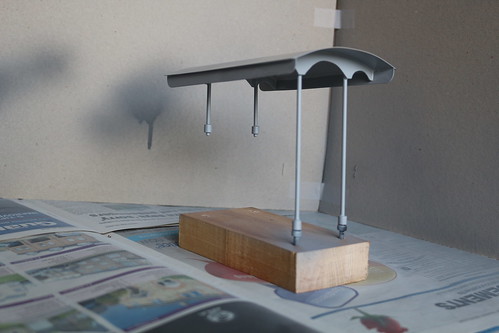
After filing away excess solder and sanding down all the brass parts I started painting by giving the entire canopy a couple of coats of etching primer from a spray can. To support the canopy during painting I re-used my support strut jig, opening up two of the holes to take M4 screws.

I forgot to take any photos during the rest of the painting. I used Humbrol enamels, thinned with white spirit. I found it quite difficult to get a satisfactory matt finish on the upper surface of the roof ("dark slate grey", no 224) but after enough coats and a gentle buff with a rag I think the result's not too bad.

Replacement canopy for Wilesco traction engine

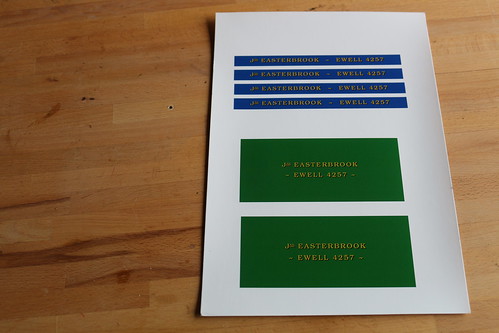
I drew some lettering for the sides of the roof using the LibreOffice "oodraw" program, and then printed the result on an A4 sheet of water slide decal paper. (I also did some lettering for a simple trailer kit I've built.)

Replacement canopy for Wilesco traction engine

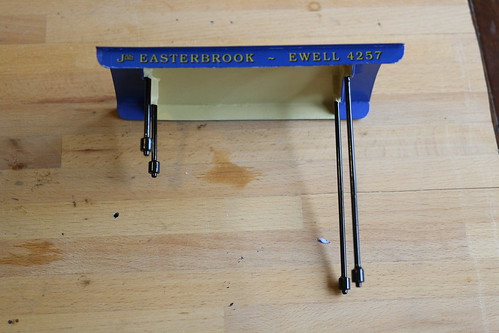
After attaching the decals there were a few bits of white showing around the edges. I touched these up with more paint after the decals had dried.

Replacement canopy for Wilesco traction engine

Replacement canopy for Wilesco traction engine

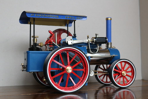
These two pictures show the canopy in place on the traction engine. I think it looks pretty good overall. The video below shows how easy it is to remove and replace, thanks to the magnets at the bottom of the support struts.

Replacement canopy for Wilesco traction engine

Wednesday, 9 November 2016

Improving my Wilesco traction engine's wheels

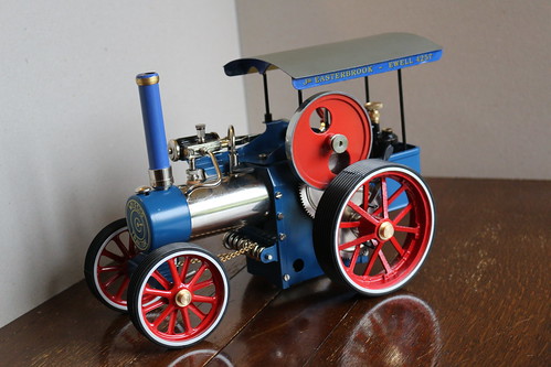
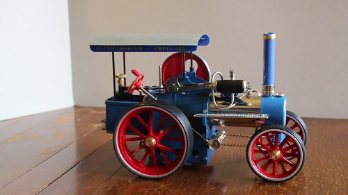
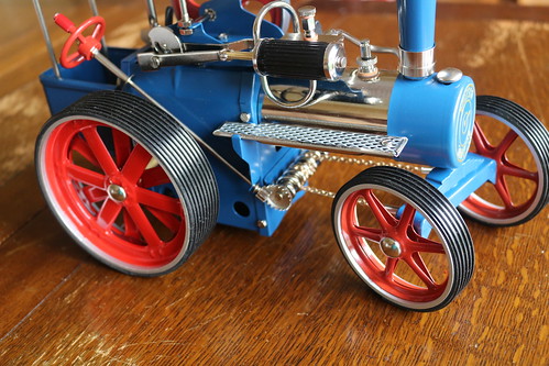
The biggest fan of Wilesco toy steam engines would have to admit that their traction engine's wheels are not particularly attractive or realistic. (Yes I know it's a toy, not a scale model.)

Wilesco toy traction engine kit

A popular way to improve the appearance of the rear wheels is to replace the pressed steel spokes with complete Mamod traction engine wheels. Mamod wheels are castings that look a lot better but can't be used directly as they're too small. Fitting them inside the Wilesco rims gets round this problem.

Improving the Wilesco traction engine wheels

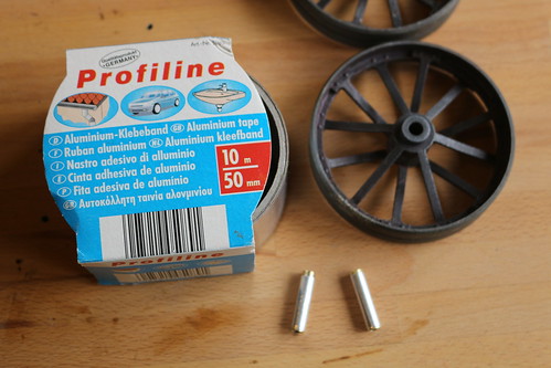
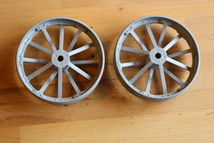
I bought a pair of old Mamod wheels on eBay. Their paint was in poor condition so I stripped them back to bare metal. The Mamod wheel's centre hole is ¼" diameter (6.35mm) compared to 5mm on the Wilesco. I cut two lengths of 6mm OD (5.1mm ID) brass tube and wound them in three layers of thin aluminium tape to make snugly fitting adaptor bushes.

Improving the Wilesco traction engine wheels Improving the Wilesco traction engine wheels

I bought a custom length axle with brass hubcaps from CJW Steam Ltd and made shorter replacements for the Wilesco brass spacers using some more of the 6mm brass tube. I then assembled everything to make sure it all fitted and that the clutch would still engage and disengage correctly.

Improving the Wilesco traction engine wheels Improving the Wilesco traction engine wheels

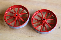
The next job was to prime and paint the Mamod wheels. I used an etching primer spray followed by two brush coats of Humbrol red gloss enamel.

Improving the Wilesco traction engine wheels

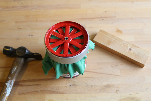
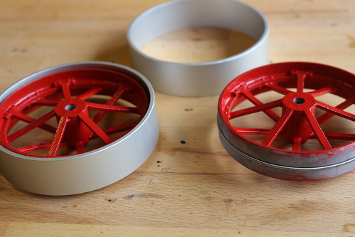
While the paint was drying I removed the Wilesco rims from their pressed steel spokes. I found a suitable size tin of paint to support the inner part of the wheel (with a bit of old T-shirt for padding) while I gently eased the rim off with a hammer and bit of wood.

Improving the Wilesco traction engine wheels

The Mamod wheels are several millimetres smaller than the Wilesco rim's inner diameter so I put a spiral drive belt (as used to drive toy steam engine accessories) around each wheel to make them a better fit. I then glued the wheels inside the rims with epoxy resin adhesive.

Improving the Wilesco traction engine wheels Improving the Wilesco traction engine wheels

Finally I filled the gap between Mamod wheel and Wilesco rim with some Milliput and, once it had set, painted it and touched up some other damage to my earlier paintwork.

Improving the Wilesco traction engine wheels

I'm very pleased with the final result. You'll notice I've also doubled the number of spokes on the front wheels. This is done by removing one of the pressed steel centres from the rim and then replacing it with a 30° offset. I also gave the front wheels a coat of the same red paint as their original colour is a slightly more orange shade of red.

Friday, 21 October 2016

Making a canopy for my Wilesco traction engine, part 2.

In a previous post I described the preliminary stages of making a canopy for my Wilesco toy traction engine. In this post I commit my design to metal.

Replacement canopy for Wilesco traction engine

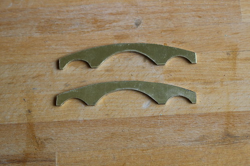
I cut the cross members from 1.5mm thick brass sheet. This was the first time I'd used a piercing saw (also known as a jeweller's saw) since my 'O' level metalwork practical exam 41 years ago. At least I didn't saw into my finger this time.

Replacement canopy for Wilesco traction engine

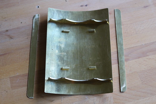
The top and sides are cut from 0.55mm brass. I bent the top around a suitable diameter plastic pipe, gradually bending it a bit further until it matched the curve of the cross members. The four short pieces of 4mm brass tube will receive the vertical supports.

Replacement canopy for Wilesco traction engine

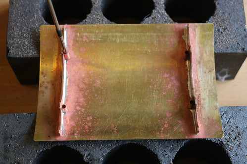
The previously assembled jig was used with four lengths of 3mm stainless steel rod to hold the brass tubes in place while each cross member was soldered.

Replacement canopy for Wilesco traction engine

Unfortunately one of the pieces of stainless steel got soldered in place, even though I was using flux that clearly says "not for use on stainless steel". I couldn't wrench it out without ripping off the brass tube, so I had to cut a new piece of tube and resolder that corner.

Replacement canopy for Wilesco traction engine

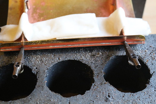
I used wet kitchen towel to prevent the cross members becoming unsoldered while I soldered the sides. I hadn't realised in advance that heating just one side of the roof would cause it to distort, so the ends of the sides are slightly separated from the top. I probably should have glued the side pieces on instead of soldering them.

Replacement canopy for Wilesco traction engine

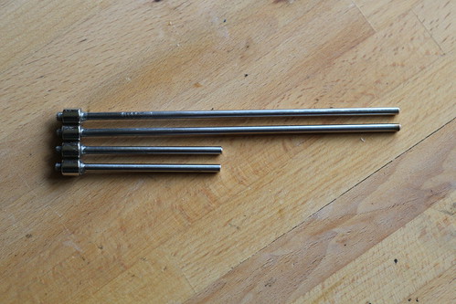
The supports are made from 3mm stainless steel rod. After cutting them to length I glued a cylindrical magnet to each one. The magnets are ¼ inch diameter with an ⅛ inch hole.

Replacement canopy for Wilesco traction engine

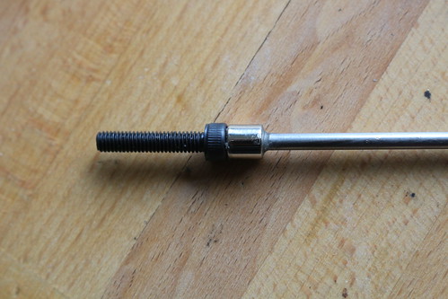
The magnets are positioned so the protruding bit of 3mm rod snugly fits the cap of an M4 socket head screw. I used a screw to hold each magnet in place while the glue set, but was careful to remove the screw before the glue had fully hardened. Some glue had worked its way into the screw cap.

Replacement canopy for Wilesco traction engine

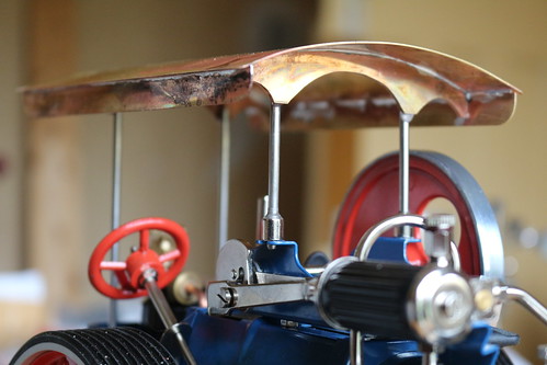
With the magnets in place I was able to fine tune the length of each support so the canopy was level and evenly supported. The front supports attach directly to the traction engine "machine plate" while the rear supports attach to M4 x 20mm socket head screws in the original canopy's mounting holes in the scuttle. (I probably should have used longer screws, bringing the heads nearer the top of the scuttle.) Once I was satisfied with the support lengths I glued them into the brass tubes.

All that's left to do is to remove excess solder and glue, then cleaning and painting.

Monday, 10 October 2016

It's a toy, not a model!

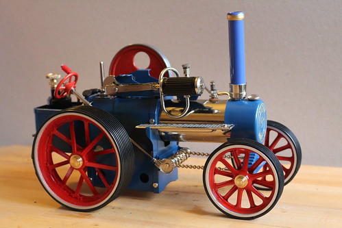
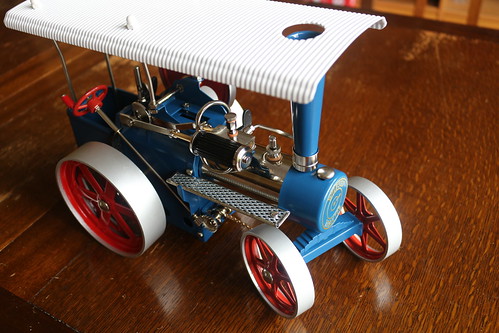
Since I bought a toy traction engine I've been thinking about all sorts of ways to improve it. I've already started scratch building a better canopy and have nearly finished making a simple trailer from a kit. In all of this it's important to remember that it's a tin-plate toy, not a scale model. Excessive detail would look out of place.

Wilesco toy traction engine kit

I can't help asking myself what sort of traction engine it's not a scale model of though. Comparing its proportions (mainly wheelbase and wheel sizes) with some of the many traction engine photos to be found on the web I reckon the best match is a Garrett steam tractor, at about 1:18 scale. Nothing else I've seen has the chimney similarly to the rear of the smoke box.


In the UK a "steam tractor" was a small traction engine (no more than 5 tons weight) that could legally be operated by just one person. They were used for light haulage, particularly timber, so Wilesco's toy log wagon is an appropriate accessory.

The most obviously wrong bit of the Wilesco toy is the flywheel. Apart from having two holes it's also much too large. I assume this is required for the engine to run properly. I've also not seen anything like the Wilesco's drip tray / gangway on a real steam tractor class engine. The most obvious omission is a belly tank, but I have plans to rectify that eventually.

The next question is what to tow? Whilst I fancy the challenge of building a heavy haulage trailer this just isn't the right sort of engine to tow it. Period photos from the 1910s and 1920s when such engines were common are not easy to find, but a typical load was nothing more than one or two 4 wheeled wagons.


This picture shows a Garrett tractor being used for timber haulage, possibly in the 1920s.


This picture shows a Taskers tractor hauling two precarious looking trailers. The high load platform and rather spindly look of these reminds me of the Mamod toy wagons which I'd previously thought were rather unrealistic.